My Portable Antenna in 2026: The Comrod APX50
For my 2026 portable operations I mainly rely on a piece of uncompromising military hardware: a 4-meter tactical vehicle whip (manufactured by the Norwegian company Comrod). Originally designed for harsh battlefield conditions and manufactured to NATO standards (country code 25 indicates Norway), this antenna is a passive monopole.
Origin and Build Quality
Unlike typical commercial ham radio verticals, this antenna is built to withstand mechanical stress, including violent wind loads and severe weather. The radiating elements are protected within thick fiberglass tubes, and the base features a massive (and heavy!) shock-absorbing spring. When assembling it, you immediately feel the difference in quality. This ruggedness is perfect for portable setups where reliability is non-negotiable—after all, the last thing you want is to arrive at a remote operating spot only to discover that a flimsy piece of equipment broke in transit…
Technical Details of the Comrod APX Series
These antennas are designed for mobile HF voice and data communication (1.6 – 30 MHz) on land vehicles and feature a highly robust construction. When fully assembled, the four fiberglass rod elements provide a total length of approximately 4.7 to 5.0 meters. Since the two Whip Middle elements (NSN 5985-25-151-5957) are identical, the antenna can also be operated in a shortened configuration. To reduce the vehicle’s visual signature during deployment, it can easily be used with just the bottom and top elements (approx. 2.6 meters).
The antenna consists of five modular pieces, making it highly transportable despite its assembled length.
- Antenna Type: Passive HF Vertical Whip
- Overall Length: Approx. 4 meters (need to measure it one day :-) )
- Frequency Range: 1.6 MHz – 30 MHz (needs an external ATU)
- Mounting & Feeding: Massive threaded base with an M8 connection bolt for the RF feed.
Component Breakdown (NATO Stock Numbers):
- Base Section:
5985-25-151-9247(Heavy-duty mount, spring, and insulator) - Bottom Element:
5985-25-151-5958(Thickest, bears the main wind load) - Middle Elements (2x):
5985-25-151-5957(Two identical extension rods) - Top Element:
5985-25-151-5956(Tapered top section)
Ham Radio Application
Because this is a pure, passive radiating element it performs well across the HF spectrum when paired with an ATU placed directly at the feed point (I use a 15cm connection here). For bands like 20m through 10m, it acts as an efficient, low-angle radiator, on lower bands like 40m (and to some extent 80m), it operates as a physically very short vertical. Note: As with any vertical monopole, the secret to its performance lies in the ground system. A proper radial field (or originally a massive vehicle ground) is mandatory.
A “Windowed Pipe” As Mounting Solution
In my densely populated corner of Germany, finding a quiet spot to deploy an antenna without drawing the nervous stares of concerned bystanders is nearly impossible. On top of that, Murphy’s Law dictates that whenever I finally have some spare time for portable operations, the weather is guaranteed to be rainy and windy.
Because of these conditions, my setup has to be two things: lightning-fast to deploy before I get soaked, and mechanically rock-solid against the wind. While the military whip should be perfect for this, its physical design presented a challenge. The antenna’s base features a massive 5cm mounting thread with an insulated RF connection bolt protruding directly from the bottom. Simply dropping it into a standard mast pipe would completely block access to the feed point. To solve this problem and ensure I could connect the ATU in seconds, I made a custom “windowed pipe” mount.
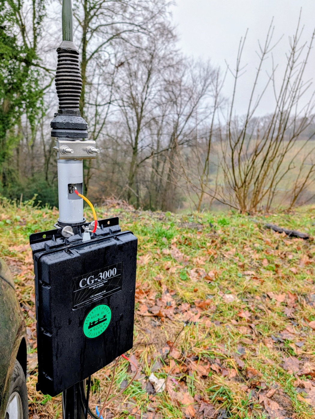
The Comrod antenna in action.
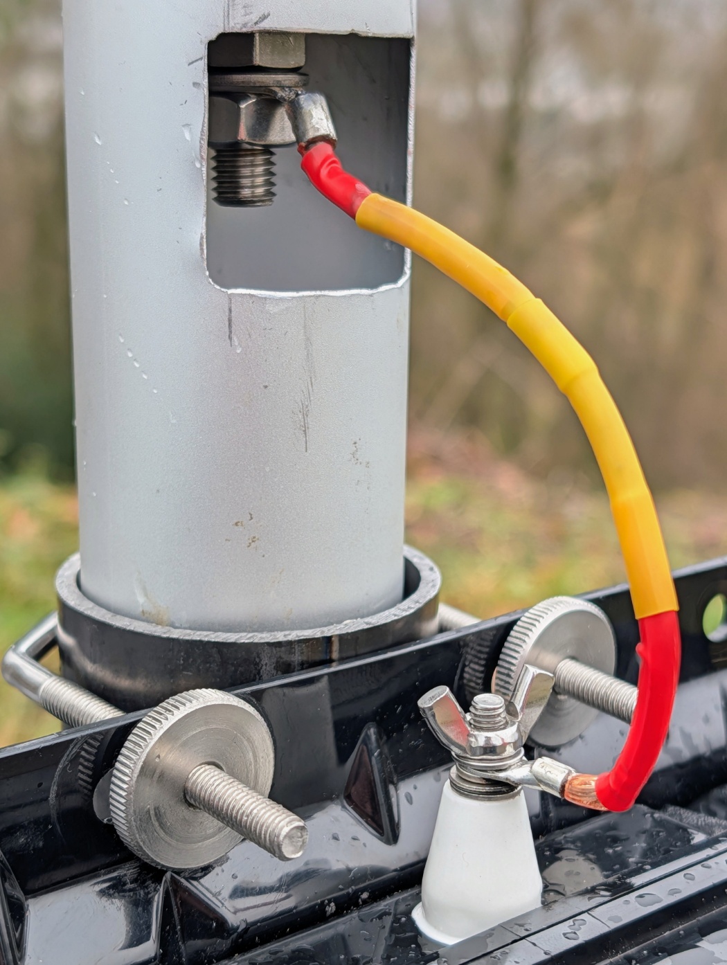
The Windowed Pipe.
The Mechanical Setup
- The Foundation: A heavy-duty drive-on tire stand acts as the primary anchor under the car wheel.
- The Modified Mast: I use a sturdy metal mast pipe (with an inner diameter just over 5cm) that fits securely into the drive-on stand. Using an angle grinder, I cut a “window” into the side of the upper pipe section, where the M8 connection bolt sits when the antenna is inserted.
- Securing the Whip: The threaded military base drops perfectly into the top of the pipe. To prevent the whip from rotating in the wind, an additional clamp holds it tight.
Electrical Integration & Weatherproofing
The automatic antenna tuner (in my case, a CG-3000) is strapped to the mast pipe directly below the cutout window.
- The Feedline: Thanks to the window, the high-voltage wire from the ATU can be bolted directly to the M8 connector. Crucial detail: I always leave a slight “drip loop” and strain relief in this short wire. When the heavy spring flexes in strong winds, you do not want any mechanical tension tearing at the ATU’s ceramic insulator.
- The Ground System: An extensive array of wire radials is connected directly to the ATU’s ground terminal and spread out across the field. Since this is a monopole, the radial field is the secret to its efficiency, especially on bands like 40m.
- Wet Weather Operations: I’ve run this setup in heavy rain already. Althrough the window exposes the RF connection - this is no problem as the bottom of my mast pipe has drainage so pooling water won’t short out the feed point!
First Field Test: ARRL DX Contest in the Rain
I took the antenna out in the pouring rain for a brief, two-hour shakedown run during the ARRL DX Contest. Timing-wise, it wasn’t ideal—the higher bands were only just beginning to open up—but impatience got the better of me. I really wanted to see how this piece of hardware would perform in real-world conditions…. And I have to say, I am absolutely thrilled with the results.
Running just 100 watts and a quick-and-dirty ground system of only four wire radials laid out on the wet grass, I was easily able to work US East Coast stations. Given how well the antenna played, I have no doubt that working the West Coast would have been possible if I could have stayed another four or five hours for propagation to peak, but unfortunately, I had to tear down and leave the spot.
Take a look at the two pictures below to compare the initial propagation prediction with the actual reality on the air:
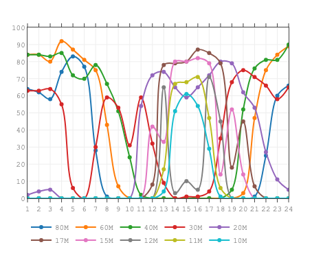
Caption: Propagation prediction see for the timeframe 1130z...1300z.
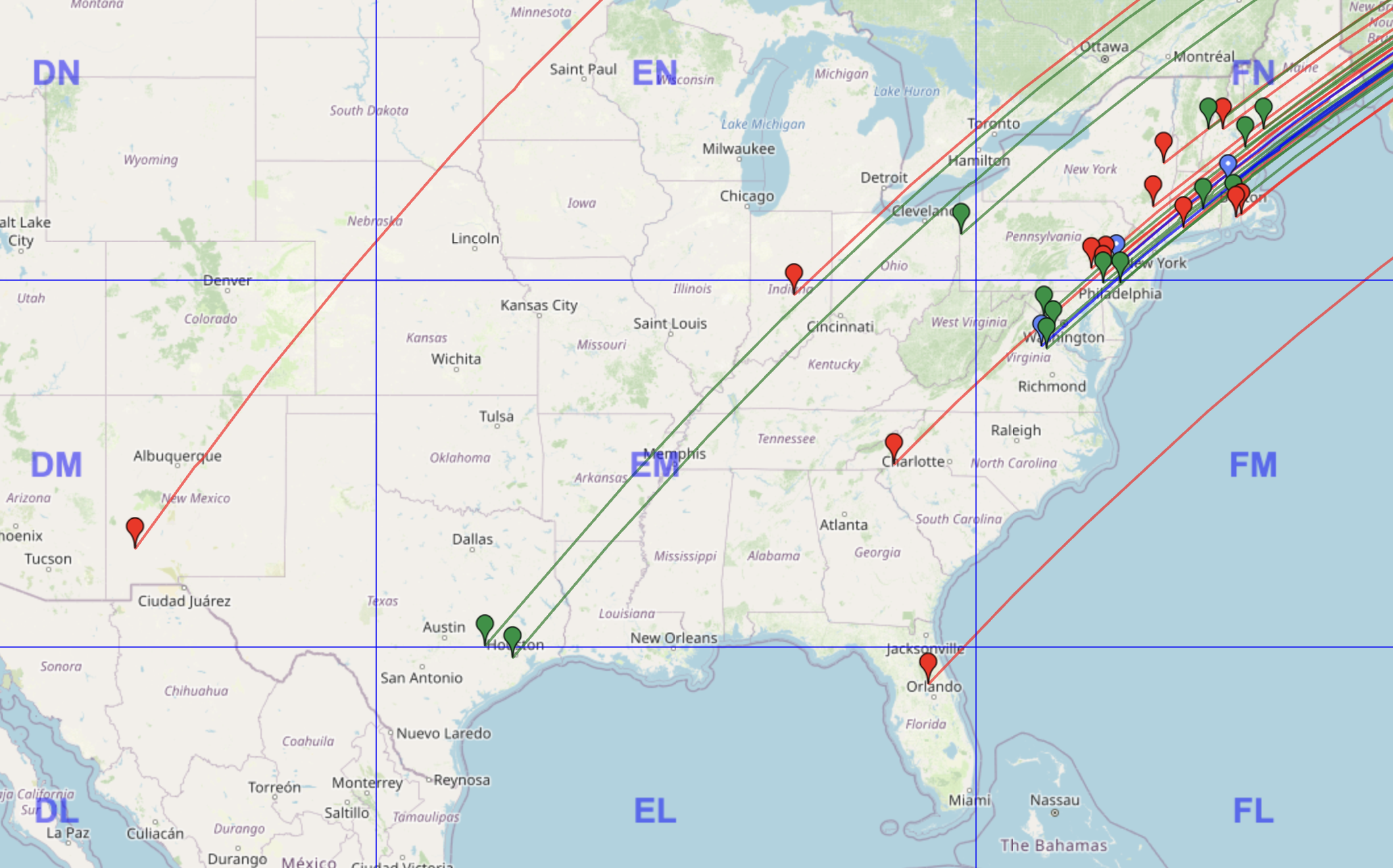
Caption: The actual reality - successful QSOs to the US East Coast: 20m (red), 15m (green), and 10m (blue)! The bands were just starting to wake up, but I had to pull the plug on the test early.